

Introduction to Diagram Design


Diagrams are one of the most important concepts for developing software. You can say diagrams are blueprints of software. Before jumping into implementing software, diagrams are needed to understand what to build and how to build it. Those diagrams help developers to work in a clean way.
Why UML is needed
Now let's understand the necessity of UML diagrams. In a real-world project, a company has different teams to do different tasks. Suppose a team's task is to design the software (not to write codes) and another team's task is to write codes for the proposed design. Now, how can the first team give ideas to the second team on how they will build the application? They can use diagrams or designs to make them understand. Now, if a team or company uses their own notation to design a diagram then it will be difficult to understand those diagrams for other people or teams. So, everyone needs to use a standard notation to design applications. UML diagrams solve this problem. UML diagrams have standard rules for design systems. Almost every company uses the UML diagram to design their projects. Thus the companies do not face any problems when a new team replaces any one of the current teams in a project. Because the newly assigned employee knows UML diagram rules and understands the notations.
Definition of UML
The full meaning of UML is Unified Modeling Language. The definition says it is an industry-standard modeling language for specifying, visualizing, and documenting the system. With the help of the UML, we can implement or show the object-oriented analysis and design graphically. It will help to understand the overall view of a system. Its notation is derived from Grady Booch's methodology for describing a set of objects and their relationships, the object modeling technique of James Rumbaugh, and the use-case methodology of Ivar Jacobson. These three persons are the creators of the UML diagram.
Types of UML diagram
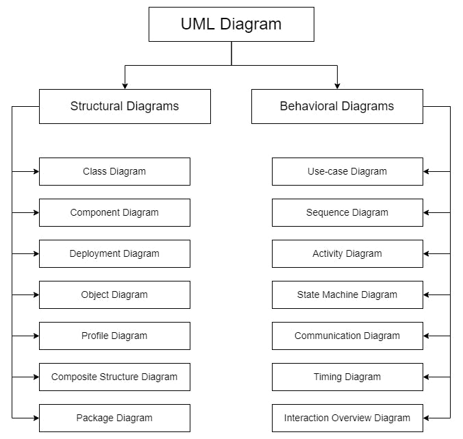
Structural Diagrams: Structural diagrams are used to model the static structure of a system. To demonstrate the structured system, attributes, operations, and relationships are used.
Behavioral Diagrams: Behavioral diagrams depict the system's dynamic behavior. The system's response to the user's input or events, interactions with other entities, data flowing, changing of internal states based on the events and inputs, etc. are described using behavioral diagrams.